Inside this tutorial, you will learn how to perform pan and tilt object tracking using a Raspberry Pi, Python, and computer vision.
One of my favorite features of the Raspberry Pi is the huge amount of additional hardware you can attach to the Pi. Whether it’s cameras, temperature sensors, gyroscopes/accelerometers, or even touch sensors, the community surrounding the Raspberry Pi has enabled it to accomplish nearly anything.
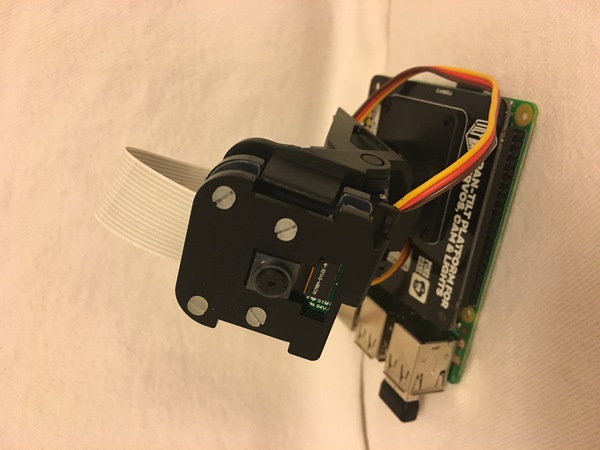
But one of my favorite add-ons to the Raspberry Pi is the pan and tilt camera.
Using two servos, this add-on enables our camera to move left-to-right and up-and-down simultaneously, allowing us to detect and track objects, even if they were to go “out of frame” (as would happen if an object approached the boundaries of a frame with a traditional camera).
Today we are going to use the pan and tilt camera for object tracking and more specifically, face tracking.
To learn how to perform pan and tilt tracking with the Raspberry Pi and OpenCV, just keep reading!
Pan/tilt face tracking with a Raspberry Pi and OpenCV
In the first part of this tutorial, we’ll briefly describe what pan and tilt tracking is and how it can be accomplished using servos. We’ll also configure our Raspberry Pi system so that it can communicate with the PanTiltHAT and use the camera.
From there we’ll also review the concept of a PID controller, a control loop feedback mechanism often used in control systems.
We’ll then will implement our PID controller, face detector + object tracker, and driver script used to perform pan/tilt tracking.
I’ll also cover manual PID tuning basics — an essential skill.
Let’s go ahead and get started!
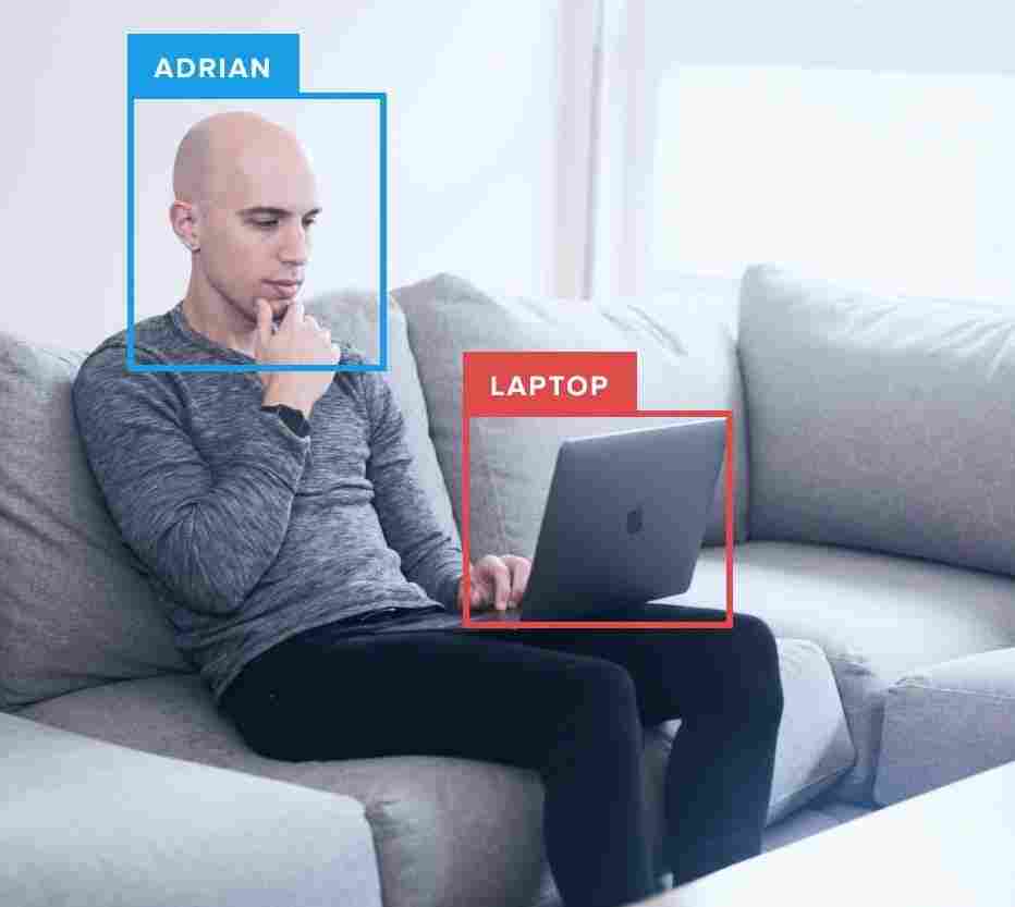
What is pan/tilt object tracking?
The goal of pan and tilt object tracking is for the camera to stay centered upon an object.
Typically this tracking is accomplished with two servos. In our case, we have one servo for panning left and right. We have a separate servo for tilting up and down.
Each of our servos and the fixture itself has a range of 180 degrees (some systems have a greater range than this).
Hardware requirements for today’s project
You will need the following hardware to replicate today’s project:
- Raspberry Pi – I recommend the 3B+ or 3B, but other models may work provided they have the same header pin layout.
- PiCamera – I recommend the PiCamera V2
- Pimoroni pan tilt HAT full kit – The Pimoroni kit is a quality product and it hasn’t let me down. Budget about 30 minutes for assembly. I do not recommend the SparkFun kit as it requires soldering and additional assembly.
- 2.5A, 5V power supply – If you supply less than 2.5A, your Pi might not have enough current causing it to reset. Why? Because the servos draw necessary current away. Get a power supply and dedicate it to this project hardware.
- HDMI Screen – Placing an HDMI screen next to your camera as you move around will allow you to visualize and debug, essential for manual tuning. Do not try X11 forwarding — it is simply too slow for video applications. VNC is possible if you don’t have an HDMI screen but I haven’t found an easy way to start VNC without having an actual screen plugged in as well.
- Keyboard/mouse – Obvious reasons.
Installing software for the PantiltHat
For today’s project, you need the following software:
- OpenCV
- smbus
- pantilthat
- imutils
Everything can easily be installed via pip except the smbus. Let’s review the steps:
Step #1: Create a virtual environment and install OpenCV
Head over to my pip install opencv blog post and you’ll learn how to set up your Raspberry Pi with a Python virtual environment with OpenCV installed. I named my virtual environment py3cv4 .
Step #2: Sym-link smbus into your py3cv4 virtual environment
Follow these instructions to install smbus :
$ cd ~/.virtualenvs/py3cv4/lib/python3.5/site-packages/
$ ln -s /usr/lib/python3/dist-packages/smbus.cpython-35m-arm-linux-gnueabihf.so smbus.so
Step #3: Enable the i2c interface as well as the camera interface
Fire up the Raspbian system config and turn on the i2c and camera interfaces (may require a reboot).
$ sudo raspi-config
# enable the i2c and camera interfaces via the menu
Step #4: Install pantilthat , imutils , and the PiCamera
Using pip, go ahead and install the remaining tools:
$ workon py3cv4
$ pip install pantilthat
$ pip install imutils
$ pip install "picamera[array]"
You should be all set from here forward!
What is a PID controller?
A common feedback control loop is what is called a PID or Proportional-Integral-Derivative controller.
PIDs are typically used in automation such that a mechanical actuator can reach an optimum value (read by the feedback sensor) quickly and accurately.
They are used in manufacturing, power plants, robotics, and more.
The PID controller calculates an error term (the difference between desired set point and sensor reading) and has a goal of compensating for the error.
The PID calculation outputs a value that is used as an input to a “process” (an electromechanical process, not what us computer science/software engineer types think of as a “computer process”).
The sensor output is known as the “process variable” and serves as input to the equation. Throughout the feedback loop, timing is captured and it is input to the equation as well.
Wikipedia has a great diagram of a PID controller:
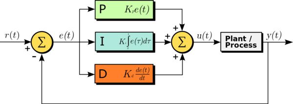
Notice how the output loops back into the input. Also notice how the Proportional, Integral, and Derivative values are each calculated and summed.
The figure can be written in equation form as:
 = K_\text{p} e(t) + K_\text{i} \int_0^t e(t') \,dt' + K_\text{d} \frac{de(t)}{dt}")
Let’s review P, I, and D:
- P (proportional): If the current error is large, the output will be proportionally large to cause a significant correction.
- I (integral): Historical values of the error are integrated over time. Less significant corrections are made to reduce the error. If the error is eliminated, this term won’t grow.
- D (derivative): This term anticipates the future. In effect, it is a dampening method. If either P or I will cause a value to overshoot (i.e. a servo was turned past an object or a steering wheel was turned too far), D will dampen the effect before it gets to the output.
Do I need to learn more about PIDs and where is the best place?
PIDs are a fundamental control theory concept.
There are tons of resources. Some are heavy on mathematics, some conceptual. Some are easy to understand, some not.
That said, as a software programmer, you just need to know how to implement one and tune one. Even if you think the mathematical equation looks complex, when you see the code, you will be able to follow and understand.
PIDs are easier to tune if you understand how they work, but as long as you follow the manual tuning guidelines demonstrated later in this post, you don’t have to be intimate with the equations above at all times.
Just remember:
- P – proportional, present (large corrections)
- I – integral, “in the past” (historical)
- D – derivative, dampening (anticipates the future)
For more information, the Wikipedia PID controller page is really great and also links to other great guides.
Project structure
Once you’ve grabbed today’s “Downloads” and extracted them, you’ll be presented with the following directory structure:
$ tree --dirsfirst
.
├── pyimagesearch
│ ├── __init__.py
│ ├── objcenter.py
│ └── pid.py
├── haarcascade_frontalface_default.xml
└── pan_tilt_tracking.py

1 directory, 5 files
Today we’ll be reviewing three Python files:
objcenter.py: Calculates the center of a face bounding box using the Haar Cascade face detector. If you wish, you may detect a different type of object and place the logic in this file.pid.py: Discussed above, this is our control loop. I like to keep the PID in a class so that I can create newPIDobjects as needed. Today we have two: (1) panning and (2) tilting.pan_tilt_tracking.py: This is our pan/tilt object tracking driver script. It uses multiprocessing with four independent processes (two of which are for panning and tilting, one is for finding an object, and one is for driving the servos with fresh angle values).
The haarcascade_frontalface_default.xml is our pre-trained Haar Cascade face detector. Haar works great with the Raspberry Pi as it requires fewer computational resources than HOG or Deep Learning.
Creating the PID controller
The following PID script is based on Erle Robotics GitBook‘s example as well as the Wikipedia pseudocode. I added my own style and formatting that readers (like you) of my blog have come to expect.
Go ahead and open pid.py. Let’s review:
# import necessary packages
import time

class PID:
	def __init__(self, kP=1, kI=0, kD=0):
		# initialize gains
		self.kP = kP
		self.kI = kI
		self.kD = kD
This script implements the PID formula. It is heavy in basic math. We don’t need to import advanced math libraries, but we do need to import time on Line 2 (our only import).
We define a class called PID on Line 4.
The PID class has three methods:
__init__: The constructor.initialize: Initializes values. This logic could be in the constructor, but then you wouldn’t have the convenient option of reinitializing at any time.update: This is where the calculation is made.
Our constructor is defined on Lines 5-9 accepting three parameters, kP , kI , and kD . These values are constants and are specified in our driver script. Three corresponding instance variables are defined in the method body.
Now let’s review initialize :
	def initialize(self):
		# initialize the current and previous time
		self.currTime = time.time()
		self.prevTime = self.currTime

		# initialize the previous error
		self.prevError = 0

		# initialize the term result variables
		self.cP = 0
		self.cI = 0
		self.cD = 0
The initialize method sets our current timestamp and previous timestamp on Lines 13 and 14 (so we can calculate the time delta in our update method).
Our self-explanatory previous error term is defined on Line 17.
The P, I, and D variables are established on Lines 20-22.
Let’s move on to the heart of the PID class — the update method:
	def update(self, error, sleep=0.2):
		# pause for a bit
		time.sleep(sleep)

		# grab the current time and calculate delta time
		self.currTime = time.time()
		deltaTime = self.currTime - self.prevTime

		# delta error
		deltaError = error - self.prevError

		# proportional term
		self.cP = error

		# integral term
		self.cI += error * deltaTime

		# derivative term and prevent divide by zero
		self.cD = (deltaError / deltaTime) if deltaTime > 0 else 0

		# save previous time and error for the next update
		self.prevtime = self.currTime
		self.prevError = error

		# sum the terms and return
		return sum([
			self.kP * self.cP,
			self.kI * self.cI,
			self.kD * self.cD])
Our update method accepts two parameters: the error value and sleep in seconds.
Inside the update method, we:
- Sleep for a predetermined amount of time on Line 26, thereby preventing updates so fast that our servos (or another actuator) can’t respond fast enough. The
sleepvalue should be chosen wisely based on knowledge of mechanical, computational, and even communication protocol limitations. Without prior knowledge, you should experiment for what seems to work best. - Calculate
deltaTime(Line 30). Updates won’t always come in at the exact same time (we have no control over it). Thus, we calculate the time difference between the previous update and now (this current update). This will affect ourcIandcDterms. - Compute
deltaError(Line 33) The difference between the providederrorandprevError.
Then we calculate our PID control terms:
cP: Our proportional term is equal to theerrorterm.cI: Our integral term is simply theerrormultiplied bydeltaTime.cD: Our derivative term isdeltaErroroverdeltaTime. Division by zero is accounted for.
Finally, we:
- Set the
prevTimeandprevError(Lines 45 and 46). We’ll need these values during our nextupdate. - Return the summation of calculated terms multiplied by constant terms (Lines 49-52).
Keep in mind that updates will be happening in a fast-paced loop. Depending on your needs, you should adjust the sleep parameter (as previously mentioned).
Implementing the face detector and object center tracker
The goal of our pan and tilt tracker will be to keep the camera centered on the object itself.
To accomplish this goal, we need to:
- Detect the object itself.
- Compute the center (x, y)-coordinates of the object.
Let’s go ahead and implement our ObjCenter class which will accomplish both of these goals:
# import necessary packages
import imutils
import cv2

class ObjCenter:
	def __init__(self, haarPath):
		# load OpenCV's Haar cascade face detector
		self.detector = cv2.CascadeClassifier(haarPath)
This script requires imutils and cv2 to be imported.
Our ObjCenter class is defined on Line 5.
On Line 6, the constructor accepts a single argument — the path to the Haar Cascade face detector.
We’re using the Haar method to find faces. Keep in mind that the Raspberry Pi (even a 3B+) is a resource-constrained device. If you elect to use a slower (but more accurate) HOG or a CNN, keep in mind that you’ll want to slow down the PID calculations so they aren’t firing faster than you’re actually detecting new face coordinates.
Note: You may also elect to use a Movidius NCS or Google Coral TPU USB Accelerator for face detection. We’ll be covering that concept in a future tutorial/in the Raspberry Pi for Computer Vision book.
The detector is initialized on Line 8.
Let’s define the update method which will find the center (x, y)-coordinate of a face:
	def update(self, frame, frameCenter):
		# convert the frame to grayscale
		gray = cv2.cvtColor(frame, cv2.COLOR_BGR2GRAY)

		# detect all faces in the input frame
		rects = self.detector.detectMultiScale(gray, scaleFactor=1.05,
			minNeighbors=9, minSize=(30, 30),
			flags=cv2.CASCADE_SCALE_IMAGE)

		# check to see if a face was found
		if len(rects) > 0:
			# extract the bounding box coordinates of the face and
			# use the coordinates to determine the center of the
			# face
			(x, y, w, h) = rects[0]
			faceX = int(x + (w / 2.0))
			faceY = int(y + (h / 2.0))

			# return the center (x, y)-coordinates of the face
			return ((faceX, faceY), rects[0])

		# otherwise no faces were found, so return the center of the
		# frame
		return (frameCenter, None)
Today’s project has two update methods so I’m taking the time here to explain the difference:
- We previously reviewed the
PIDupdatemethod. This method performs the PID calculations to help calculate a servo angle to keep the face in the center of the camera’s view. - Now we are reviewing the
ObjCcenterupdatemethod. This method simply finds a face and returns its center coordinates.
The update method (for finding the face) is defined on Line 10 and accepts two parameters:
frame: An image ideally containing one face.frameCenter: The center coordinates of the frame.
The frame is converted to grayscale on Line 12.
From there we perform face detection using the Haar Cascade detectMultiScale method.
On Lines 20-26 we check that faces have been detected and from there calculate the center (x, y)-coordinates of the face itself.
Lines 20-24 makes an important assumption: we assume that only one face is in the frame at all times and that face can be accessed by the 0-th index of rects .
Note: Without this assumption holding true additional logic would be required to determine which face to track. See the “Improvements for pan/tilt face tracking with the Raspberry Pi” section of this post. where I describe how to handle multiple face detections with Haar.
The center of the face, as well as the bounding box coordinates, are returned on Line 29. We’ll use the bounding box coordinates to draw a box around the face for display purposes.
Otherwise, when no faces are found, we simply return the center of the frame (so that the servos stop and do not make any corrections until a face is found again).
Our pan and tilt driver script
Let’s put the pieces together and implement our pan and tilt driver script!
Open up the pan_tilt_tracking.py file and insert the following code:
# import necessary packages
from multiprocessing import Manager
from multiprocessing import Process
from imutils.video import VideoStream
from pyimagesearch.objcenter import ObjCenter
from pyimagesearch.pid import PID
import pantilthat as pth
import argparse
import signal
import time
import sys
import cv2

# define the range for the motors
servoRange = (-90, 90)
On Line 2-12 we import necessary libraries. Notably we’ll use:
ProcessandManagerwill help us withmultiprocessingand shared variables.VideoStreamwill allow us to grab frames from our camera.ObjCenterwill help us locate the object in the frame whilePIDwill help us keep the object in the center of the frame by calculating our servo angles.pantilthatis the library used to interface with the Raspberry Pi Pimoroni pan tilt HAT.
Our servos on the pan tilt HAT have a range of 180 degrees (-90 to 90) as is defined on Line 15. These values should reflect the limitations of your servos.
Let’s define a “ctrl + c” signal_handler :
# function to handle keyboard interrupt
def signal_handler(sig, frame):
	# print a status message
	print("[INFO] You pressed `ctrl + c`! Exiting...")

	# disable the servos
	pth.servo_enable(1, False)
	pth.servo_enable(2, False)

	# exit
	sys.exit()
This multiprocessing script can be tricky to exit from. There are a number of ways to accomplish it, but I decided to go with a signal_handler approach.
The signal_handler is a thread that runs in the background and it will be called using the the signal module of Python. It accepts two arguments, sig and the frame . The sig is the signal itself (generally “ctrl + c”). The frame is not a video frame and is actually the execution frame.
We’ll need to start the signal_handler thread inside of each process.
Line 20 prints a status message. Lines 23 and 24 disable our servos. And Line 27 exits from our program.
You might look at this script as a whole and think “If I have four processes, and signal_handler is running in each of them, then this will occur four times.”
You are absolutely right, but this is a compact and understandable way to go about killing off our processes, short of pressing “ctrl + c” as many times as you can in a sub-second period to try to get all processes to die off. Imagine if you had 10 processes and were trying to kill them with the “ctrl + c” approach.
Now that we know how our processes will exit, let’s define our first process:
def obj_center(args, objX, objY, centerX, centerY):
	# signal trap to handle keyboard interrupt
	signal.signal(signal.SIGINT, signal_handler)

	# start the video stream and wait for the camera to warm up
	vs = VideoStream(usePiCamera=True).start()
	time.sleep(2.0)

	# initialize the object center finder
	obj = ObjCenter(args["cascade"])

	# loop indefinitely
	while True:
		# grab the frame from the threaded video stream and flip it
		# vertically (since our camera was upside down)
		frame = vs.read()
		frame = cv2.flip(frame, 0)

		# calculate the center of the frame as this is where we will
		# try to keep the object
		(H, W) = frame.shape[:2]
		centerX.value = W // 2
		centerY.value = H // 2

		# find the object's location
		objectLoc = obj.update(frame, (centerX.value, centerY.value))
		((objX.value, objY.value), rect) = objectLoc

		# extract the bounding box and draw it
		if rect is not None:
			(x, y, w, h) = rect
			cv2.rectangle(frame, (x, y), (x + w, y + h), (0, 255, 0),
				2)

		# display the frame to the screen
		cv2.imshow("Pan-Tilt Face Tracking", frame)
		cv2.waitKey(1)
Our obj_center thread begins on Line 29 and accepts five variables:
args: Our command line arguments dictionary (created in our main thread).objXandobjY: The (x, y)-coordinates of the object. We’ll continuously calculate this.centerXandcenterY: The center of the frame.
On Line 31 we start our signal_handler .
Then, on Lines 34 and 35, we start our VideoStream for our PiCamera , allowing it to warm up for two seconds.
Our ObjCenter is instantiated as obj on Line 38. Our cascade path is passed to the constructor.
From here, our process enters an infinite loop on Line 41. The only way to escape out of the loop is if the user types “ctrl + c” as you’ll notice no break command.
Our frame is grabbed and flipped on Lines 44 and 45. We must flip the frame because the PiCamera is physically upside down in the pan tilt HAT fixture by design.
Lines 49-51 set our frame width and height as well as calculate the center point of the frame. You’ll notice that we are using .value to access our center point variables — this is required with the Manager method of sharing data between processes.
To calculate where our object is, we’ll simply call the update method on obj while passing the video frame . The reason we also pass the center coordinates is because we’ll just have the ObjCenter class return the frame center if it doesn’t see a Haar face. Effectively, this makes the PID error 0 and thus, the servos stop moving and remain in their current positions until a face is found.
Note: I choose to return the frame center if the face could not be detected. Alternatively, you may wish to return the coordinates of the last location a face was detected. That is an implementation choice that I will leave up to you.
The result of the update is parsed on Line 55 where our object coordinates and the bounding box are assigned.
The last steps are to draw a rectangle around our face (Lines 58-61) and to display the video frame (Lines 64 and 65).
Let’s define our next process, pid_process :
def pid_process(output, p, i, d, objCoord, centerCoord):
	# signal trap to handle keyboard interrupt
	signal.signal(signal.SIGINT, signal_handler)

	# create a PID and initialize it
	p = PID(p.value, i.value, d.value)
	p.initialize()

	# loop indefinitely
	while True:
		# calculate the error
		error = centerCoord.value - objCoord.value

		# update the value
		output.value = p.update(error)
Our pid_process is quite simple as the heavy lifting is taken care of by the PID class. Two of these processes will be running at any given time (panning and tilting). If you have a complex robot, you might have many more PID processes running.
The method accepts six parameters:
output: The servo angle that is calculated by our PID controller. This will be a pan or tilt angle.p,i, andd: Our PID constants.objCoord: This value is passed to the process so that the process has access to keep track of where the object is. For panning, it is an x-coordinate. Similarly, for tilting, it is a y-coordinate.centerCoord: Used to calculate ourerror, this value is just the center of the frame (either x or y depending on whether we are panning or tilting).
Be sure to trace each of the parameters back to where the process is started in the main thread of this program.
On Line 69, we start our special signal_handler .
Then we instantiate our PID on Line 72, passing the each of the P, I, and D values.
Subsequently, the PID object is initialized (Line 73).
Now comes the fun part in just two lines of code:
- Calculate the
erroron Line 78. For example, this could be the frame’s y-center minus the object’s y-location for tilting. - Call
update(Line 81), passing the new error (and a sleep time if necessary). The returned value is theoutput.value. Continuing our example, this would be the tilt angle in degrees.
We have another thread that “watches” each output.value to drive the servos.
Speaking of driving our servos, let’s implement a servo range checker and our servo driver now:
def in_range(val, start, end):
	# determine the input value is in the supplied range
	return (val >= start and val <= end)

def set_servos(pan, tlt):
	# signal trap to handle keyboard interrupt
	signal.signal(signal.SIGINT, signal_handler)

	# loop indefinitely
	while True:
		# the pan and tilt angles are reversed
		panAngle = -1 * pan.value
		tiltAngle = -1 * tlt.value

		# if the pan angle is within the range, pan
		if in_range(panAngle, servoRange[0], servoRange[1]):
			pth.pan(panAngle)

		# if the tilt angle is within the range, tilt
		if in_range(tiltAngle, servoRange[0], servoRange[1]):
			pth.tilt(tiltAngle)
Lines 83-85 define an in_range method to determine if a value is within a particular range.
From there, we’ll drive our servos to specific pan and tilt angles in the set_servos method.
Our set_servos method will be running in another process. It accepts pan and tlt values and will watch the values for updates. The values themselves are constantly being adjusted via our pid_process .
We establish our signal_handler on Line 89.
From there, we’ll start our infinite loop until a signal is caught:
- Our
panAngleandtltAnglevalues are made negative to accommodate the orientation of the servos and camera (Lines 94 and 95). - Then we check each value ensuring it is in the range as well as drive the servos to the new angle (Lines 98-103).
That was easy.
Now let’s parse command line arguments:
# check to see if this is the main body of execution
if __name__ == "__main__":
	# construct the argument parser and parse the arguments
	ap = argparse.ArgumentParser()
	ap.add_argument("-c", "--cascade", type=str, required=True,
		help="path to input Haar cascade for face detection")
	args = vars(ap.parse_args())
The main body of execution begins on Line 106.
We parse our command line arguments on Lines 108-111. We only have one — the path to the Haar Cascade on disk.
Now let’s work with process safe variables and start our processes:
	# start a manager for managing process-safe variables
	with Manager() as manager:
		# enable the servos
		pth.servo_enable(1, True)
		pth.servo_enable(2, True)

		# set integer values for the object center (x, y)-coordinates
		centerX = manager.Value("i", 0)
		centerY = manager.Value("i", 0)

		# set integer values for the object's (x, y)-coordinates
		objX = manager.Value("i", 0)
		objY = manager.Value("i", 0)

		# pan and tilt values will be managed by independed PIDs
		pan = manager.Value("i", 0)
		tlt = manager.Value("i", 0)
Inside the Manager block, our process safe variables are established. We have quite a few of them.
First, we enable the servos on Lines 116 and 117. Without these lines, the hardware won’t work.
Let’s look at our first handful of process safe variables:
- The frame center coordinates are integers (denoted by
"i") and initialized to0(Lines 120 and 121). - The object center coordinates, also integers and initialized to
0(Lines 124 and 125). - Our
panandtltangles (Lines 128 and 129) are integers that I’ve set to start in the center pointing towards a face (angles of0degrees).
Now is where we’ll set the P, I, and D constants:
		# set PID values for panning
		panP = manager.Value("f", 0.09)
		panI = manager.Value("f", 0.08)
		panD = manager.Value("f", 0.002)

		# set PID values for tilting
		tiltP = manager.Value("f", 0.11)
		tiltI = manager.Value("f", 0.10)
		tiltD = manager.Value("f", 0.002)
Our panning and tilting PID constants (process safe) are set on Lines 132-139. These are floats. Be sure to review the PID tuning section next to learn how we found suitable values. To get the most value out of this project, I would recommend setting each to zero and following the tuning method/process (not to be confused with a computer science method/process).
With all of our process safe variables ready to go, let’s launch our processes:
		# we have 4 independent processes
		# 1. objectCenter  - finds/localizes the object
		# 2. panning       - PID control loop determines panning angle
		# 3. tilting       - PID control loop determines tilting angle
		# 4. setServos     - drives the servos to proper angles based
		#                    on PID feedback to keep object in center
		processObjectCenter = Process(target=obj_center,
			args=(args, objX, objY, centerX, centerY))
		processPanning = Process(target=pid_process,
			args=(pan, panP, panI, panD, objX, centerX))
		processTilting = Process(target=pid_process,
			args=(tlt, tiltP, tiltI, tiltD, objY, centerY))
		processSetServos = Process(target=set_servos, args=(pan, tlt))

		# start all 4 processes
		processObjectCenter.start()
		processPanning.start()
		processTilting.start()
		processSetServos.start()

		# join all 4 processes
		processObjectCenter.join()
		processPanning.join()
		processTilting.join()
		processSetServos.join()

		# disable the servos
		pth.servo_enable(1, False)
		pth.servo_enable(2, False)
Each process is kicked off on Lines 147-153, passing required process safe values. We have four processes:
- A process which finds the object in the frame. In our case, it is a face.
- A process which calculates panning (left and right) angles with a PID.
- A process which calculates tilting (up and down) angles with a PID.
- A process which drives the servos.
Each of the processes is started and then joined (Lines 156-165).
Servos are disabled when all processes exit (Lines 168 and 169). This also occurs in the signal_handler just in case.
Tuning the pan and tilt PIDs independently, a critical step
That was a lot of work!
Now that we understand the code, we need to perform manual tuning of our two independent PIDs (one for panning and one for tilting).
Tuning a PID ensures that our servos will track the object (in our case, a face) smoothly.
Be sure to refer to the manual tuning section in the PID Wikipedia article.
The article instructs you to follow this process to tune your PID:
- Set
kIandkDto zero. - Increase
kPfrom zero until the output oscillates (i.e. the servo goes back and forth or up and down). Then set the value to half. - Increase
kIuntil offsets are corrected quickly, knowing that too high of a value will cause instability. - Increase
kDuntil the output settles on the desired output reference quickly after a load disturbance (i.e. if you move your face somewhere really fast). Too muchkDwill cause excessive response and make your output overshoot where it needs to be.
I cannot stress this enough: Make small changes while tuning.
Let’s prepare to tune the values manually.
Even if you coded along through the previous sections, make sure you use the “Downloads” section of this tutorial to download the source code to this guide.
Transfer the zip to your Raspberry Pi using SCP or another method. Once on your Pi, unzip the files.
We will be tuning our PIDs independently, first by tuning the tilting process.
Go ahead and comment out the panning process in the driver script:
		# start all 4 processes
		processObjectCenter.start()
		#processPanning.start()
		processTilting.start()
		processSetServos.start()

		# join all 4 processes
		processObjectCenter.join()
		#processPanning.join()
		processTilting.join()
		processSetServos.join()
From there, open up a terminal and execute the following command:
$ python pan_tilt_tracking.py --cascade haarcascade_frontalface_default.xml
You will need to follow the manual tuning guide above to tune the tilting process.
While doing so, you’ll need to:
- Start the program and move your face up and down, causing the camera to tilt. I recommend doing squats at your knees and looking directly at the camera.
- Stop the program + adjust values per the tuning guide.
- Repeat until you’re satisfied with the result (and thus, the values). It should be tilting well with small displacements, and large changes in where your face is. Be sure to test both.
At this point, let’s switch to the other PID. The values will be similar, but it is necessary to tune them as well.
Go ahead and comment out the tilting process (which is fully tuned).
From there uncomment the panning process:
		# start all 4 processes
		processObjectCenter.start()
		processPanning.start()
		#processTilting.start()
		processSetServos.start()

		# join all 4 processes
		processObjectCenter.join()
		processPanning.join()
		#processTilting.join()
		processSetServos.join()
And once again, execute the following command:
$ python pan_tilt_tracking.py --cascade haarcascade_frontalface_default.xml
Now follow the steps above again to tune the panning process.
Pan/tilt tracking with a Raspberry Pi and OpenCV
With our freshly tuned PID constants, let’s put our pan and tilt camera to the test.
Assuming you followed the section above, ensure that both processes (panning and tilting) are uncommented and ready to go.
From there, open up a terminal and execute the following command:
$ python pan_tilt_tracking.py --cascade haarcascade_frontalface_default.xml
Once the script is up and running you can walk in front of your camera.
If all goes well you should see your face being detected and tracked, similar to the GIF below:
As you can see, the pan/tilt camera tracks my face well.
Improvements for pan/tilt tracking with the Raspberry Pi
There are times when the camera will encounter a false positive face causing the control loop to go haywire. Don’t be fooled! Your PID is working just fine, but your computer vision environment is impacting the system with false information.
We chose Haar because it is fast, however just remember Haar can lead to false positives:
- Haar isn’t as accurate as HOG. HOG is great but is resource hungry compared to Haar.
- Haar is far from accurate compared to a Deep Learning face detection method. The DL method is too slow to run on the Pi and real-time. If you tried to use it panning and tilting would be pretty jerky.
My recommendation is that you set up your pan/tilt camera in a new environment and see if that improves the results. For example, we were testing the face tracking, we found that it didn’t work well in a kitchen due to reflections off the floor, refrigerator, etc. However, when we aimed the camera out the window and I stood outside, the tracking improved drastically because ObjCenter was providing legitimate values for the face and thus our PID could do its job.
What if there are two faces in the frame?
Or what if I’m the only face in the frame, but consistently there is a false positive?
This is a great question. In general, you’d want to track only one face, so there are a number of options:
- Use the confidence value and take the face with the highest confidence. This is not possible using the default Haar detector code as it doesn’t report confidence values. Instead, let’s explore other options.
- Try to get the
rejectLevelsandrejectWeights. I’ve never tried this, but the following links may help: - Grab the largest bounding box — easy and simple.
- Select the face closest to the center of the frame. Since the camera tries to keep the face closest to the center, we could compute the Euclidean distance between all centroid bounding boxes and the center (x, y)-coordinates of the frame. The bounding box closest to the centroid would be selected.
What's next? We recommend PyImageSearch University.

86+ total classes • 115+ hours hours of on-demand code walkthrough videos • Last updated: July 2026
★★★★★ 4.84 (128 Ratings) • 16,000+ Students Enrolled
I strongly believe that if you had the right teacher you could master computer vision and deep learning.
Do you think learning computer vision and deep learning has to be time-consuming, overwhelming, and complicated? Or has to involve complex mathematics and equations? Or requires a degree in computer science?
That’s not the case.
All you need to master computer vision and deep learning is for someone to explain things to you in simple, intuitive terms. And that’s exactly what I do. My mission is to change education and how complex Artificial Intelligence topics are taught.
If you're serious about learning computer vision, your next stop should be PyImageSearch University, the most comprehensive computer vision, deep learning, and OpenCV course online today. Here you’ll learn how to successfully and confidently apply computer vision to your work, research, and projects. Join me in computer vision mastery.
Inside PyImageSearch University you'll find:
- ✓ 86+ courses on essential computer vision, deep learning, and OpenCV topics
- ✓ 86 Certificates of Completion
- ✓ 115+ hours hours of on-demand video
- ✓ Brand new courses released regularly, ensuring you can keep up with state-of-the-art techniques
- ✓ Pre-configured Jupyter Notebooks in Google Colab
- ✓ Run all code examples in your web browser — works on Windows, macOS, and Linux (no dev environment configuration required!)
- ✓ Access to centralized code repos for all 540+ tutorials on PyImageSearch
- ✓ Easy one-click downloads for code, datasets, pre-trained models, etc.
- ✓ Access on mobile, laptop, desktop, etc.
Summary
In this tutorial, you learned how to perform pan and tilt tracking using a Raspberry Pi, OpenCV, and Python.
To accomplish this task, we first required a pan and tilt camera.
From there we implemented our PID used in our feedback control loop.
Once we had our PID controller we were able to implement the face detector itself.
The face detector had one goal — to detect the face in the input image and then return the center (x, y)-coordinates of the face bounding box, enabling us to pass these coordinates into our pan and tilt system.
From there the servos would center the camera on the object itself.
I hope you enjoyed today’s tutorial!
To download the source code to this post, and be notified when future tutorials are published here on PyImageSearch, just enter your email address in the form below!

Download the Source Code and FREE 17-page Resource Guide
Enter your email address below to get a .zip of the code and a FREE 17-page Resource Guide on Computer Vision, OpenCV, and Deep Learning. Inside you'll find my hand-picked tutorials, books, courses, and libraries to help you master CV and DL!